See next page.

Speed Measurement
01 void _ISR_PSV _IC1Interrupt(void)
02 {
03 _IC1IF = 0; // interrupt flag reset
04 Ic1CurrPeriod = IC1BUF;//capture the current value
05 if (Tmr2OvflwCount1 == 0) // TMR2 overflowed?
06 {// see
Microchip AN545
07 Ic1Period +=
(Ic1CurrPeriod - Ic1PrevPeriod);
08 }
09 else
10 {
11 Ic1Period+=(Ic1CurrPeriod+(0xFFFF-Ic1PrevPeriod));
12 Tmr2OvflwCount1 = 0;
13 }
14 Ic1PrevPeriod =
Ic1CurrPeriod;
15
16 if (QEI1CONbits.UPDN)
17 {//the
samples are algebraically added according
18 //to _UPDN bit, to also know the speed direction.
19 Ic1Indx ++;
20 }
21 else
22 {
23 Ic1Indx --;
24 }
25 }
THIS PARAMETERS ARE VALID FOR LINO ROBOTIC PLATFORM.
HERE JUST AS AN EXAMPLE ON HOW TO CALCULATE THEM
Motor speed = nominal 4.000 rpm @ 12V. Maximum 5.500 with a 4S LiPo battery pack
Encoder = 512 cpr
Gear reduction ratio = 25:1
Wheel speed = 220 rpm Max
Encoder pulses for each wheel turn = 12,800
Wheel diameter = 120mm -> circumference = 377mm
Space for each encoder pulse 1x mode Delta S = 0.029452431mm
Space for each encoder pulse 2x mode Delta S = 0.014726216mm
Space for each encoder pulse 4x mode Delta S = 0.007363108mm
Maximum sped = circumference * rpm / 60 = 377mm * 220 / 60 = 138cm/s
Maximum encoder frequency = (200 * 12,800) / 60 = 47KHz
Minimum encoder pulse duration = 21.3us
Maximum QEI frequency 4x = 47 KHz * 4 = 188KHz
Maximum quantity of pulses in 1ms in 4x mode = 188 -> 1 pulse every 5.32us
Minimum speed = 377mm * 3.2 / 60 = 2cm/s
Minimum encoder frequency = (3.2 * 12,800) / 60 = 680Hz
Maximum encoder pulse duration = 1.47ms
Minimum QEI frequency 4x mode = 680Hz * 4 = 2.73KHz
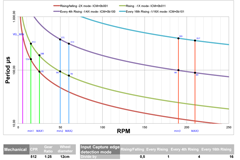
When the 1ms interrupt occurs the procedure computes the mean speed by averaging (summation/index) all the samples captured. In the 1ms period, the samples are averaged from a minimum of 1 (@ 2 rpm) to a maximum of 13 times (@ 230 rpm), but the total number of Timer2 pulses captured is always close to 30,000. This grants a good compromise between performances and quantization error.
If the speed falls below a fixed threshold (VEL_MIN_PID) the PID cycle arise to 10ms.
1 // Peripheral PIN selection **********
2 // Unlock Registers
3 //************************************
4 asm volatile ( "mov #OSCCONL, w1 \n"
5 "mov #0x45, w2 \n"
6 "mov #0x57, w3 \n"
7 "mov.b w2, [w1] \n"
8 "mov.b w3, [w1] \n"
9 "bclr OSCCON, #6 ");
10 //************************************
11 // Configure Input Functions
12 //***************************
13 // Assign IC1 To Pin RP10
14 RPINR7bits.IC1R = 10;
15
16 //***************************
17 // Assign IC2 To Pin RP6
18 RPINR7bits.IC2R = 6;
19
20 //***************************
21 // Assign QEA1 To Pin RP10
22 RPINR14bits.QEA1R = 10;
23
24 //***************************
25 // Assign QEB1 To Pin RP11
26 RPINR14bits.QEB1R = 11;
27
28 //***************************
29 // Assign QEA2 To Pin RP6
30 RPINR16bits.QEA2R = 6;
31
32 //***************************
33 // Assign QEB2 To Pin RP5
34 RPINR16bits.QEB2R
= 5;
35 ......
36 //************************************
37 // Lock Registers
38 asm volatile ( "mov #OSCCONL, w1 \n"
39 "mov #0x45, w2 \n"
40 "mov #0x57, w3 \n"
41 "mov.b w2, [w1] \n"
42 "mov.b w3, [w1] \n"
43 "bset OSCCON, #6");
44 // ******** Peripheral PIN selection
In order to compute the speed in m/s (meter per second) in a very short time, some constants are computed just once at the beginning. Let's explain the optimization procedure step by step.
Defining:
SPACE_ENC_1X = space covered in one encoder pulse in 1X mode (see here for different modes)
IcIndx = number of pulses in 1ms
TCY = Single TMR2 period = 1 / FCY (with prescaler = 1)
IcPeriod = summation of periods occurred in 1ms
Space = SPACE_ENC_1X * IcIndx (total space traveled in 1ms)
Time = TCY * IcPeriod (the exact sampling time, close to 1ms)
V = Space/Time (mean speed in 1ms)
Simplifying:
V = (SPACE_ENC_1X * IcIndx) / (TCY * IcPeriod) = (SPACE_ENC_1X / TCY) * (IcIndx / IcPeriod) =
= (SPACE_ENC_1X * FCY) * (IcIndx / IcPeriod)
= Kvel * (IcIndx / IcPeriod)
Kvel = SPACE_ENC_1X * (FCY) to obtain speed in m/s
A further optimization is obtained using a Q15 fixed point value, instead of float, for the Kvel constant. This is achieved multiplying its value by 2^15 just at compiling.
The integer elaboration is much faster and the final result is already
multiplied by 2^15, (i.e. in fractional format) for PID routine, saving even more time at each iteration. The C30 PID library in fact, uses all the power of the dsPIC DSP core (see Microchip Code Example CE019), working with Q15 variables, a very good compromise between speed and precision.
This method requires an overall time of 20us on a 30Mips dsPIC. Even less with
FCY = 40MHz.
…
const long KvelLong = 13268300; // Kvel << 15
long VelLong; // speed in a "long"
VelLong = KvelLong*IcIndxTmp/IcPeriodTmp;
PID_MES
= (VelLong); // speed measured in m/s (fractional)
…
With the Peripherals Pin Selection capability of the dsPIC33F, a single pin of the chip can be used for both a QEI channel and IC input, using the simple code listed to the right.
The IC module measures the time between two encoder pulses, by creating a snapshot in a buffer for the value of a free running timer. See Microchip application note AN545 for details.
At each encoder pulse the IC module generates an interrupt. The simple and fast Interrupt Service Routine (ISR) listed to the left, counts how many encoder ticks occurred (index), this value is proportional to the space traveled.
With the summation of all the values for ICBUF register, it returns also a value proportional to the time elapsed.