
Speed Measurement
As seen in the previous page, the Input Capture module catches the time values from a 16bit timer. A motor with a closed loop control can run at a speed as low as 60 rpm and as high as 6000 rpm. In my specific case (512 cpr encoder) it means a count every 2ms at the lower speed and every 20us at the higher speed. To have a good speed control we need at least a PID cycle every 1 ms, meaning no less than an IC sample in the same period to have a real speed value. In the aforementioned situation, we have not enough counts at the lower limit and too much interrupts for the MCU at the higher limit. Using an higher CPR (Count Per Revolution) encoder is better for the low speeds but worst for the high zone.
A good compromise between precision and performance could be achieved using the different Input Capture module edge detection modes. This, in practice, acts as a prescaler allowing an higher dynamic range for IC with a motor that runs also at a very low speed.
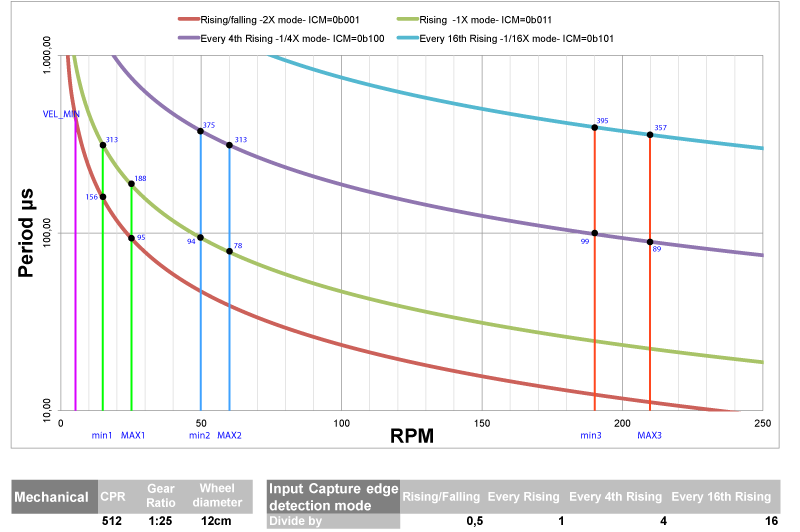
The graph above shows the relation between the wheel speed (i.e. after the gear reduction) in rpm and the encoder period (meaning also interrupts period for the MCU) in μs, at different IC configurations. For clarity purposes the Y axis is in logarithmic scale.
The dsPIC33F series DSC Input Capture module can be configured (using ICxCON: Input Capture x Control Register) in different edge detection modes. It can capture the TMR value at each edge (rising and falling) of the encoder signal, effectively doubling the input frequency and, therefore, cutting by half the period. The 1X mode is obtained capturing at each rising edge, 1/4X every 4th edge and 1/16X every 16th edge.
ICM<2:0>: Input Capture x Mode Select bits
101 = Capture mode, every 16th rising edge
100 = Capture mode, every 4th rising edge
011 = Capture mode, every rising edge
001 = Capture mode, every edge – rising and falling
000 = Input Capture module turned off
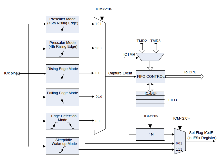
From Microchip dsPIC33F Family reference document:
"Section 12. Input Capture" DS70198D
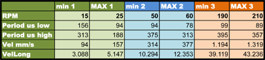
Let's analyze this very practical configuration. Looking to the graph at the 100 μs line on period axis, we can find some thresholds useful to achieve a good optimization between interrupts frequency and number of capture samples to average in 1ms. After the speed has been computed as explained in the previous page, the program can check if the "rpm-IC mode" pair is set up at the best, switching to another IC mode if not.
The switch cannot be simply done around a single
threshold for each mode. This could lead to a very dangerous up and down oscillation if the motor runs exactly at that speed. An hysteresis is created instead, instructing the program to switch to the next mode if "max" threshold has been passed and to the previous mode only under the "min" threshold.
01 //ICM<2:0>:Input Capture Mode Select bits
02 #defineIC_MODE1 0b001 // 2X mode
03 #defineIC_MODE2 0b011 // 1X mode
04 #defineIC_MODE3 0b100 // 1/4X mode
05
06 #defineKVELLONG_1 19301945 //
2X mode
07 #defineKVELLONG_2 38603891 //
1X mode
08 #defineKVELLONG_3 154415562 // 1/4X mode
09
10 #defineMIN1 6.177 // VelLong @ 30 RPM
11 #defineMAX1 10.294 // VelLong @ 50 RPM
12 #defineMIN2 20.589 // VelLong @ 100 RPM
13 #defineMAX2 24.706 // VelLong @ 120 RPM
14
15 //Kvel = SPACE_ENC*(FCY) for speed in m/s
16 long KvelLong = KVELLONG_1; // Kvel*2^15
17 long VelLong; // speed in a "long"
18
19 ...
20 // Speed computation and PID
procedure
21 // Measured Speed in m/s(fract)
22 VelLong = KvelLong*IcIndxTmp/IcPeriodTmp;
23 PID_MES=(VelLong);//PID Process Variable
24
25 switch IC1CONbits.ICM
26 {
27 case IC_MODE1:
28 if(VelLong >= MAX1)
29 {
30 IC1CONbits.ICM = 0; // turn off
31 KvelLong = KVELLONG_2;
32 IC1CONbits.ICM = IC_MODE2;
33 }
34 break;
35
36 case IC_MODE2:
37 if(VelLong < MIN1)
38 {
39 IC1CONbits.ICM
= 0; // turn off
40 KvelLong = KVELLONG_1;
41 IC1CONbits.ICM
= IC_MODE1;
42 }
43 else if(VelLong >= MAX2)
44 {
45 IC1CONbits.ICM
= 0; // turn off
46 KvelLong = KVELLONG_3;
47 IC1CONbits.ICM
= IC_MODE3;
48 }
49 break;
50
51 case IC_MODE3:
52 if(VelLong < MIN2)
53 {
54 IC1CONbits.ICM
= 0; // turn off
55 KvelLong = KVELLONG_2;
56 IC1CONbits.ICM
= IC_MODE2;
57 }
58 break;
59
60 default:
61 IC1CONbits.ICM
= 0; // turn off
62 KvelLong = KVELLONG_1;
63 IC1CONbits.ICM
= IC_MODE1;
64 break;
65 }
66 ...