dsNavCon
This is the application that remotely controls the dsNavCon board from a Mac/PC via serial communication through a couple of XBee devices as described in block diagram.
Main Panel
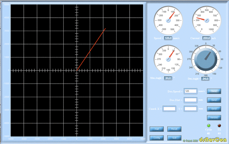
The main panel performs telemetry showing on the grid the path followed by the robot, as estimated by odometry, in a +/- 5000 mm field and displaying some other important values read on the board.
The gauges show the measured values:
- MesSpeed in a +/- 500 mm/s range, the mean value of the two wheel's speed (the speed of the center of the platform).
- MesCurrent in mA.
- MesAngle, as extimated by odometry.
The desired values can be set in different ways:
Mode A, DesAngle is set with the knob, DesSpeed is set with the input field and confirmed with "Send" button. The vehicle runs indefinitely in the desired direction with the desired speed.
Mode B, The desired final coordinates are entered through CoordX and CoordY input fields. Distance and orientation are computed as a function of the current coordinates and the destination coordinates. The speed is computed by DistPid as a function of distance from the target. The vehicle runs until the target is reached.
Mode C, DesAngle is set with the knob. The speed is computed by DistPid as a function of desired distance entered through DesDist field value. The vehicle runs until the target is reached.
Version button requests the current version of the firmware on dsNavCon board.
Halt button is for emergency use only. It stops both motors without any deceleration ramp. It is not safe for the gears.
Reset button requests a restart sequence on all the MCUs on the board. For security reason it must be sent three times subsequently in order to be accepted by the board.
Config button switches to configuration panel.
Green LED indicates the measures request cycle. Every 333 ms, all values are requested to the board, displayed on the gauges and plotted on the graph.
Red LED flashes whenever a transmission is requested pushing a button.
The number below green LED shows the program main loop execution time in ms, averaged every 100 cycles. Just as an indication of how fast the program is executed by that particular computer.
The number below red LED shows the number of RX errors occurred. The communication protocol is described on dsODO firmware page.
The program is written using Processing open source programming language and environment, with the aids of Interfascia graphical user interface library.
The graphic objects have been drawn with Adobe Photoshop and Adobe Illustrator.
They are available here in .ai and .psd layered format, allowing any modification.
The source is available as a Processing sketch.
Processing exports the program as a Java standalone application as:
Mac OSX application Linux(x86) application Windows application and as Java APPLET that runs in a browser with the limitations already mentioned.


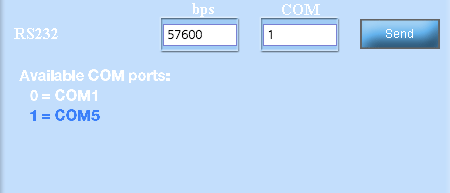
RS232 conf Win version
On Windows operating system, the list is displayed as appears on the image to the right.
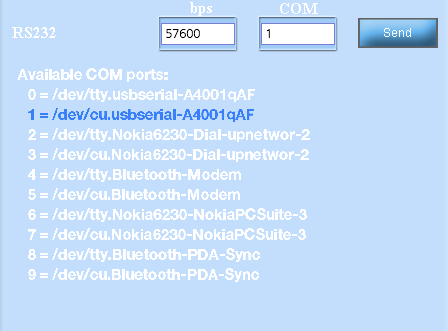
RS232 conf Unix version
(Mac OSX, Linux)
Once started, the console gets a list of all comunication ports available. The right one can be choosen typing the order number in "COM" input field.
If a wrong number is typed or if the port is not available, a "99" is displayed on input field.
On Unix based operating systems each port has two devices:
/dev/tty.xxx
/dev/cu.xxx
in this case the valid one is /dev/cu.xxx
Simulation
A working simulation example of this console can be started as a Java APPLET. Buttons and gauges execute simulated functions to have an idea of how the console runs if connected to the board. Try to enter a value for the speed and rotate the knob to see what happens.
Due to security issues requested when an applet runs in a browser, functions that have access to computer resources are disabled. Therefore the configuration saving and loading on config panel and every RS232 operation are simulated.
Configuration Panel
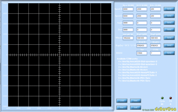
In the configuration panel can be defined and sent to the board all the parameters that depends on mechanical characteristics of the vehicle in order to be saved on MCUs EEPROMs.
All values are multiplied by a costant to keep easier the protocol with the board.
- Kp, Ki, Kd for all the PID procedures on the dsNavCon board (Speed, Angle and Distance) multiplied by 10000. The actual range is 0-0.9999 (here indicated as 0-9999).
- Axle size, the distance between the center of the two wheels, expressed in tenth of microns
(in the example 1852222 means 185.2222 mm).
- Space for each wheel encoder pulse in 4x mode, expressed in pico meters
(in the example 5061455 means 0,005061455 mm).
- Kvel costant for the two wheels. It is needed by the Motor Controllers in order to compute speed.
an explanation on how to obtain this value can be found here.
All the costants can be permanently saved to an restored from a config.txt file with "Load" and "Save" buttons. If no file is present a new one with example parameters will be created.
Calibration Procedures
Once the meaning of each parameter is known, a brief explanation on how to choose the right values.
PID costants. There are tons of documents on Internet about the "right" PID calibration procedure. Most of them are valid. A simple method, more applicable in this situation, is explained in Microchip code example CE019:
Using Proportional Integral Derivative (PID) controllers in Closed-loop Control Systems
The four PIDs are indipendent, so they can be set up separately. First of all we can take care of the speed PID of one Motor Controller, changing Kp, Ki, Kd values in sequence until the motor runs smoothly, responding quickly to the commands and without overshoot. The other motor will probably run fine with the same constants.
After the speed can be regulated accurately, the right K values for Angle PID first and Distance PID after, can be found with the same logic.
Axle size can be measured with a caliper.
Ksp, see the note below. See also “descrEng.txt” file in MPLAB project for a more detailed description.
Kvel = Ksp2x * FCY * 2^15 as described here
FOLLOWING PARAMETERS ARE VALID FOR RINO ROBOTIC PLATFORM.
HERE JUST AS AN EXAMPLE ON HOW TO CALCULATE THEM
--------------------------------------------------------------------------------------------------------------
Motor speed = 6.000 rpm
Encoder = 300 cpr
Gear reduction ratio = 30:1
Wheel speed = 200 rpm
Encoder pulses for each wheel turn = 9.000 (300 * 30)
Wheel diameter = 58mm -> circumference = 182,2123739mm
Space for each encoder pulse 1x mode = 0,020245819mm
Space for each encoder pulse 2x mode = 0,01012291mm = Ksp 2x =
Wheel_circumference / (Encoder_pulses_for_each_wheel_turn * 2)
Space for each encoder pulse 4x mode = 0,005061455mm = Ksp =
Wheel_circumference / (Encoder_pulses_for_each_wheel_turn * 4)
Maximum speed = circumference * rpm / 60 = 182,212mm * 200 / 60 = 60cm/s
--------------------------------------------------------------------------------------------------------------
The Axle, Ksp, Kvel parameters, once measured on the robot with a caliper, must be fine-tuned to make the vehicle go straight, turning the right angle and running the right distance. A first tuning can be obtained comparing the position displayed on console with the position really measured on field. A more accurate method is UMBmark:
A Method for Measuring, Comparing, and Correcting Dead-reckoning Errors in Mobile Robots.
developed at University of Michigan.

