dsNavCon
Main Panel
Only the differences with the previous version will be focused.
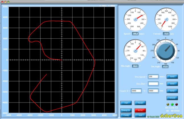
The field is now configurable in size through the configuration panel. Two more buttons added, "Debug on" button activates a debug mode on dsNavCon33 board, the values received from the console are the same as trasmitted not the real ones, meaning that if I set 200mm/s for speed I'll receive 200, setting 30° on orientation knob the same value will be diplayed on mes angle gauge. This is just to debug comunication between console and robot. "RxOn" button activates receive procedures on console. It cannot be activated if the comm parameters are not set in configuration panel.
RX LED flashes everytime a valid packet is received. Cycle LED flashes with the period set in configuration panel, it shows the activation of every TX-RX procedure (requesting for parameters). TX LED indicates the transimission of a packet different from scheduled one, i.e. when a setting value is transmitted using knob or buttons, not on parameters request.
The numbers below LEDs are for debugging and analisys purposes. The first value is transmitted from dsNavCon33 board, it's an estimation of the time, in percentage, the DSC spends in idle loop, it's useful to understand how much the DSC is loaded during its real job. The second number is the time (in ms) required by the console software to perform a full cycle (mean value), it depends on the computer the console is running on and how many other programs are running on it. Of course this is the minimum time that can be set in configuration for cycle duration. The third number shows how many times a communication timeout occurred, i.e. packet lost because of any reason.


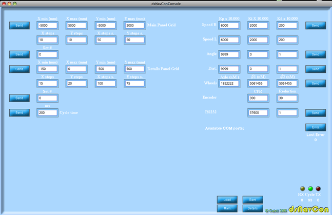
Config Panel
There are some differences also for the configuration panel. Now the grids for Main and Details panel can be user defined and some presets can be used with "Set #" fields. The last field on the left is the period in ms for the parameters request cycle towards the navigation board. The constant parameters for wheels, angle and encoders can be set in a "human" way, the conversion will be done by software before sending. The "Error" button resets the communication error LED on the navigation board requesting the latest error code.
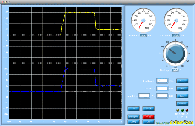
Detail Panel
This is new. It shows the actual value for speed and current on each motor, not the mean value as on Main panel. It is very useful for calibration of K parameters on speed PID procedures.

Downloads
Also this new version of the program is written using Processing open source programming language and environment, with the aids of Interfascia graphical user interface library. Be sure to download the latest version, right now no more in beta.
The graphic objects have been drawn with Adobe Photoshop and Adobe Illustrator.
They are available here in .ai and .psd layered format, allowing any modification.
The source is available as a Processing sketch.
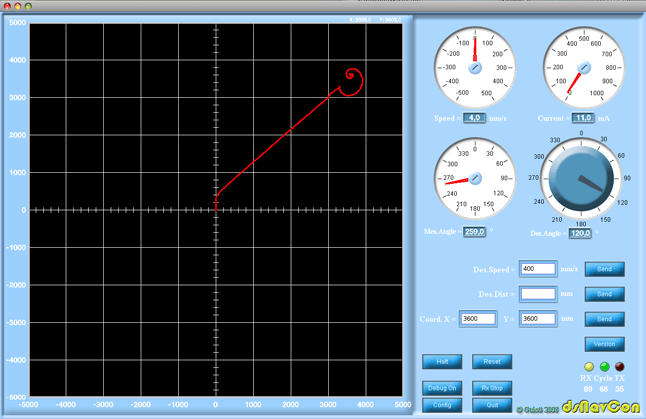
Just for fun
A funny example of how a bad configuration can generate a beautiful picture plotting the path. With wrong Kp, Ki, Kd parameters the approch to the goal results in an infinite spiral loop around the point.
