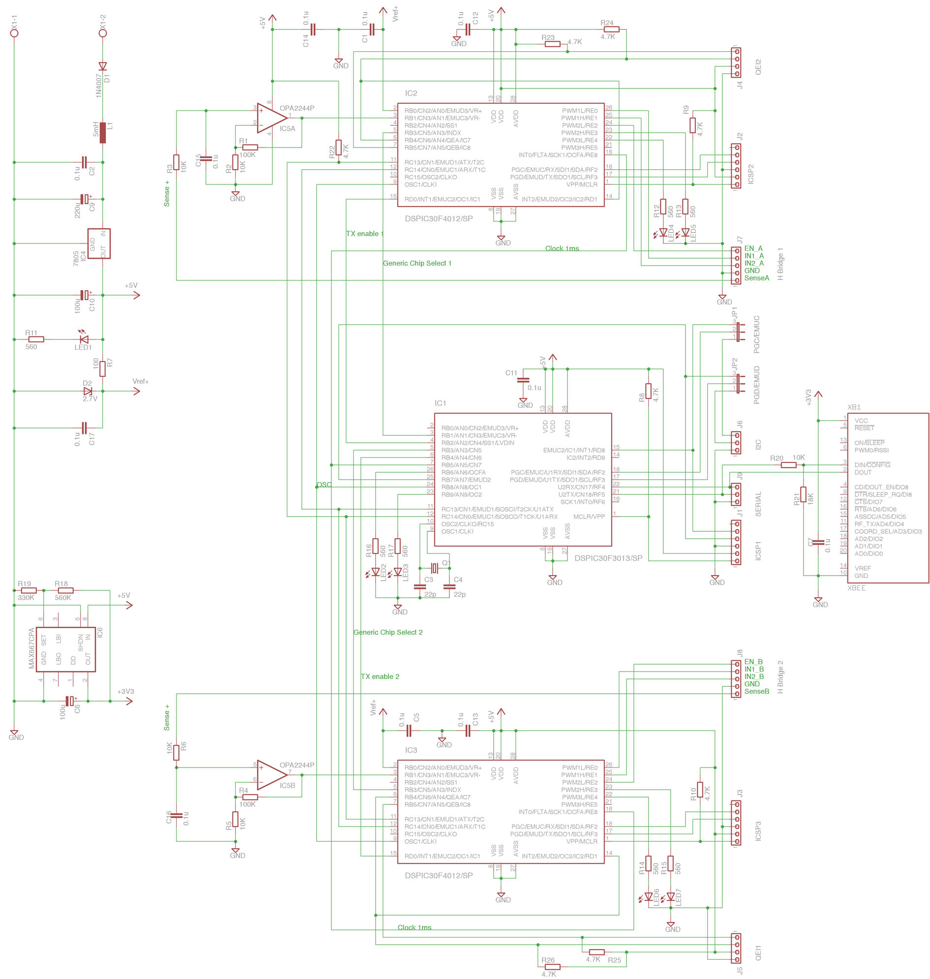
dsNavCon
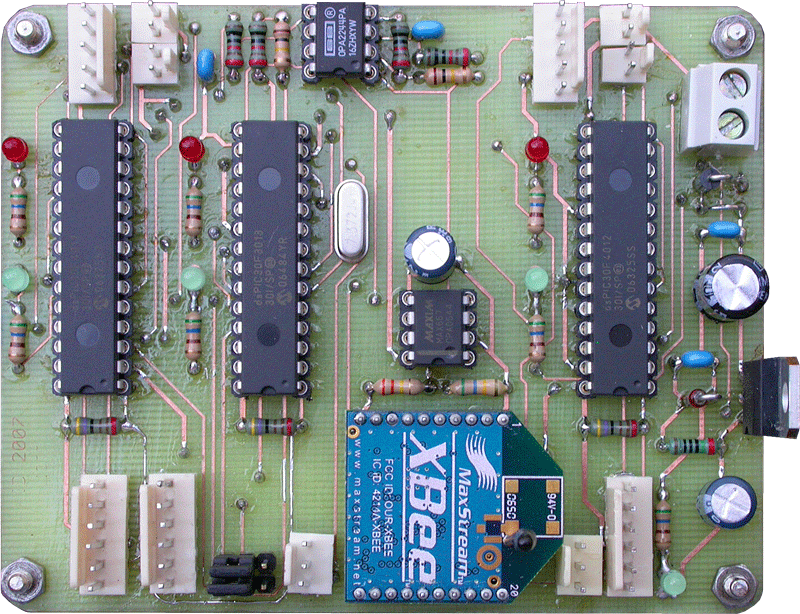
Five ICs can be seen on it: a dsPIC30F3013 as Supervisor, a couple of dsPIC30F4012 as Motor Controllers (by Microchip), a Maxim MAX667 voltage regulator to drop the 5V power supply down to 3.3V for ZigBee RF modem and a Texas Instruments OPA2244 dual operational amplifier to rise the 0-0.27V range voltage available on the H-bridge current sensing resistors, to a 0-2.7V range voltage, suitable for the dsPIC30F4012 A/D converter.


Below some links to the high resolution version of the PCB layers printout, as well as the link to the whole project (schematich diagram and PCB) realized with CadSoft EAGLE.
The board is realized withe the free version of CadSoft EAGLE, so it is double layered and 80 x 100 mm sized (half EuroCard): the maximum allowed dimensions.
It is designed to be made at home by anyone with just some simple tools. The via-holes are not metalized but they are connected top to bottom layer through a piece of wire or by soldering both sides of the sockets pins and components leadouts. This requires some special care on components placement and trace routing, in order to have enough room for soldering iron tip.
A more professional look and a smaller PCB may be obtained with SMT components, but this would require more skill and it is beyond the scope of this project.
As described in the block diagram page, this board is the "heart" of movement system. Together with the dual H-bridge and two rotary incremental encoders, it takes care of speed and position of the robot, controlling the motors.