LEDs Matrix
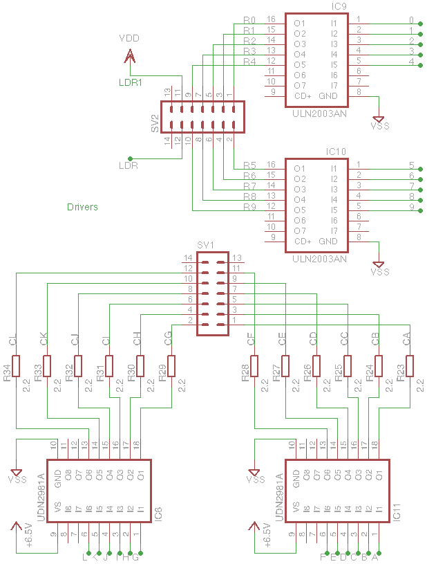
The synchronization of the signals is very important, even with a 10 x 12 only matrix. On a 100Hz scan rate even the microseconds are difficult to deal with. You have to take care of the delay times of the drivers too. The UDN2981 (used to drive the columns on the high side) has a more than 3us switch off delay. The ULN2003 (on the rows to the low side) is ten times lower. With a 10Mips MCU it's enough to move the ON or OFF code even a bit later to cause an overlap of the signals. Just few microseconds of ON time it's enough to have a weak but visible light on the high brightness LEDs. The dead band must be carefully considered.
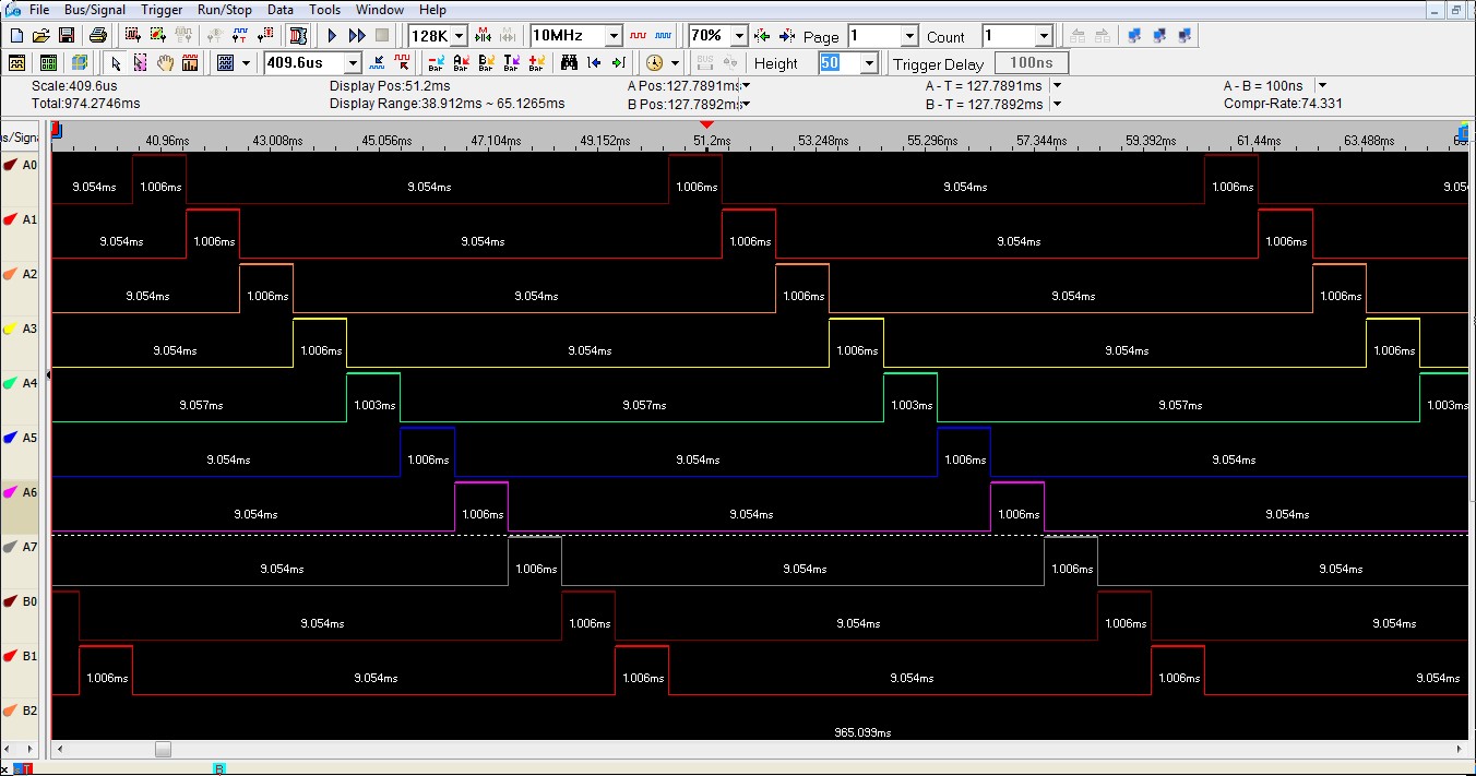
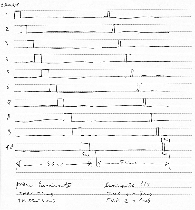
The rows signals.
These are the signals that scan the 10 rows keeping each one high for 1ms: 1ms x 10 = 10ms = 100Hz.
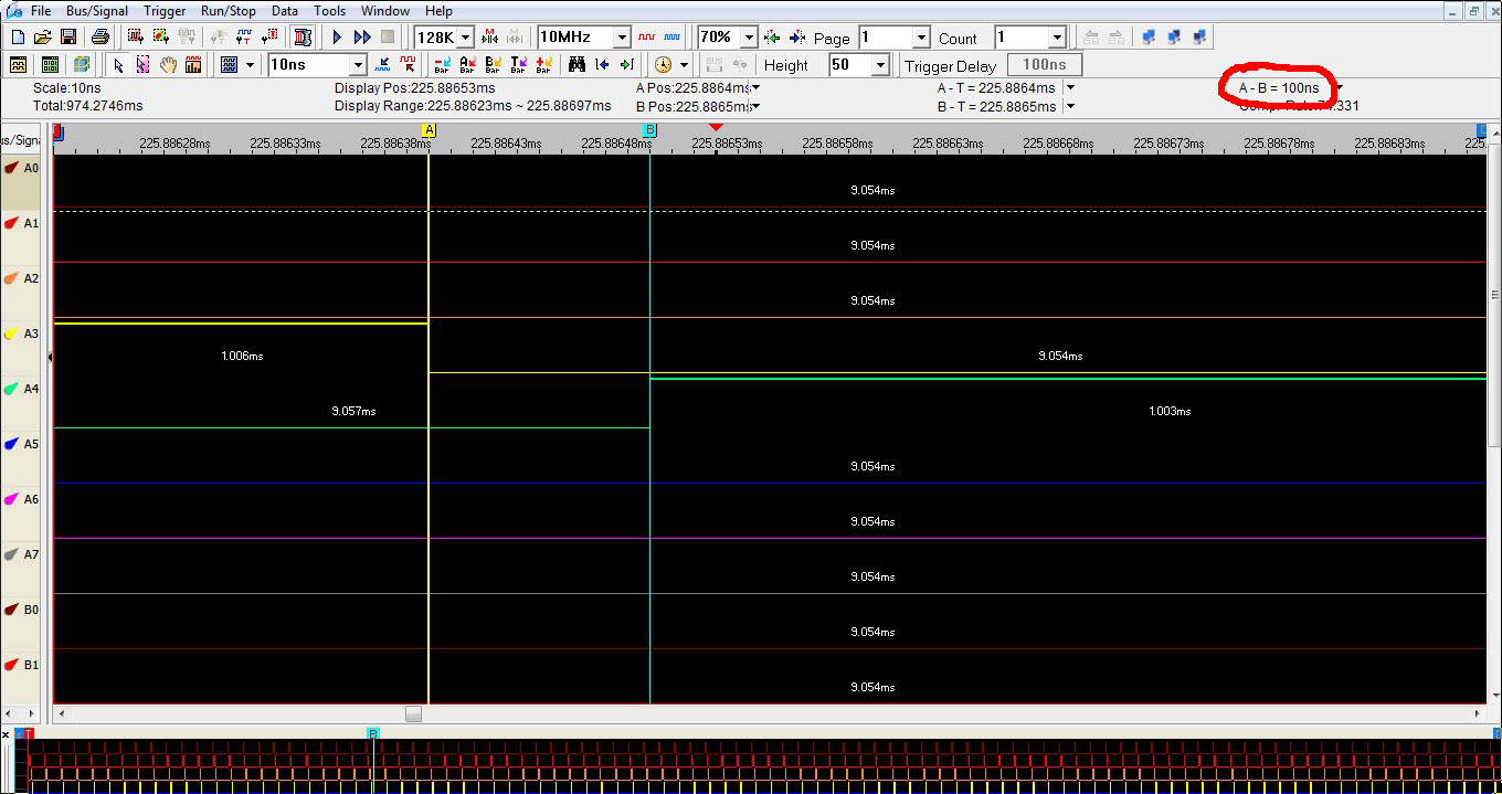
In this picture a row and a column signal with a 100ns dead-band. After some more tests, I decided to increase even more this time.
Those high brightness white LEDs require 20mA to work correctly. With a 10 rows multiplexing they are ON for 1/10 of all the frame time, resulting in a lower brightness. In theory they should be driven with a 10 times higher current to have the right brightness. But the practice is never so linear.
E.g.: TMR3 period = 1ms (in order to have a 10ms frame period = 100Hz frame rate), if TMR1 = 500us the duty cycle is 50%, if its period is 1ms the duty cycle is 100%, always with a scan rate of 100Hz.
Anyway, it's better to stop the max brightness to 99% to avoid overlap with the next row scan causing a "shadow effect" due to the switch off delay of the drivers.
All the previous calculations are valid to have the top of the brightness. In order to avoid an annoying total light in a dark room together with good visibility in a sunny place, the brightness (i.e.: the PWM duty cycle) must be automatically controlled reading the ambient light with a Light Dependent Resistor.
A full test of the matrix displaying some dynamic patterns and even some characters adding to the code a 5x7 characters generator.
In this video the duty cycle is fixed at 50%.


To better understand all the behavior of the circuit, a Logic Analyzer has been very useful.
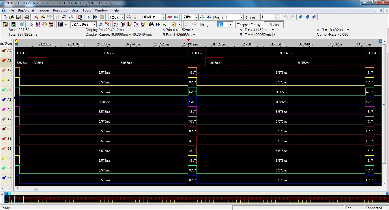
The columns signals
A0 and A1 are the first two rows signals. The others are related to the columns from A to L. They are ON for 0.5ms obtaining a 50% duty cycle. In this example all the row 0 is lighted at half brightness.
Using a further timer available in the PIC18F it's possible to implement the PWM brightness regulation without hardware complication. Using the classic PWM peripheral I would need more drivers on top of the actual. A mosfet or something similar suitable for the sum of all the currents.
Using the timer you can do all of that at software level. One timer (TMR3) is used to drive the matrix multiplexing, switching on the next row and lighting-up the columns corresponding to the word to be displayed. In the TMR3 Interrupt Service Routine it's started the TMR1 in one-shot mode with a period pre-computed according to the desired duty-cycle. When TMR1 overflows it switches off all the columns. In few words: TMR3 switches on and TMR1 switches off.
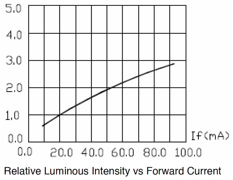
Relative Luminous Intensity vs Forward Current from a generic white LED.
We can see that with 2.5 multiplier for the current (50mA) we have only a doubling of the luminous intensity. With 4x current only 2.7 times brightness. Not linear at all and impossible to reach the (theoretically) needed 10 times.
A good choice to avoid an early dead
of the LEDs, could be 50mA.