dsNavCon
Dead reckoning by odometry
Optimization of the general algorithm
for a use in a DSC or MCU based system
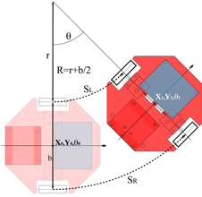
Once we have the information about the distance traveled by each wheel in a discrete-time update (odometry), we can estimate the position coordinates of the robot with the same periodicity without any external reference (dead reckoning).
The mathematical background and a deep explanation of the general method used, can be found on G.W. Lucas’ paper A Tutorial and Elementary Trajectory Model for the Differential Steering System of Robot Wheel Actuators, available on Internet: http://rossum.sourceforge.net/papers/DiffSteer/DiffSteer.html
With the same meaning for the symbols and terms used by Lucas, we can start from the equations [3] and [5]:
![]()


doing some steps in order to optimize the elaboration procedures for a computer program.
For each discrete time interval the system measures the number of pulses generated by the encoders. Knowing the space relative to a single encoder tick, we can calculate the distance traveled by the wheels ![]() in the time t.
in the time t.
Being: velocity=Space/time:
![]()
![]()
and, according to Lucas:

we can write:
![]()
![]()
At time ![]() the differences with the coordinates at
the differences with the coordinates at ![]() are:
are:
![]()
![]()
![]()
Cumulating each delta-value in its own variable we know the current coordinates (position and orientation) of the platform.
In order to avoid computational errors (divide by zero) and waste of the controller time, a check has to be done in advance on both![]() and
and ![]() variables. Defining a quasi-zero value
variables. Defining a quasi-zero value ![]() that takes care of minimal mechanical and computational approximations we have:
that takes care of minimal mechanical and computational approximations we have:
- If ![]() , the platform is traveling in a nearly straight line and we can use without approximations the method in [6] from Lucas’ paper:
, the platform is traveling in a nearly straight line and we can use without approximations the method in [6] from Lucas’ paper:
![]()
![]()
![]()
![]()
- If ![]() , the platform is pivoting around its own vertical axis without moving, so:
, the platform is pivoting around its own vertical axis without moving, so:
![]()
![]()
Below some C language code as an example of how to implement the algorithm described.
Code Example
Global definitions:
// costants for traveled distance calculation: SPACE_ENC_4X in mm
float Ksp[2] = {0.00506145483078356,0.00506145483078356};
float Axle = 185.2222; // base width, distance between center of the wheels
float SemiAxle = 92.6111; // Axle / 2
int SpTick[2] = {0,0}; // distance traveled by a wheel as encoder pulses
float Spmm[2] = {0,0}; // distance traveled by a wheel as mm(SpTick[x]*Ksp[x])
float Space = 0; // total distance traveled by the robot
#define SPMIN 0.003 // TO CHECK. Minimum value to perform odometry
float CosPrev = 1; // previous value for Cos(Theta)
float SinPrev = 0; // previous value for Sin(Theta)
float PosX = 0; // X position coordinate
float PosY = 0; // X position coordinate
float Theta = 0; // Current orientation angle
#define TWOPI 6.2831853072
............................................................
Function:
void DeadReckoning(void)
{ float CosNow, SinNow;// current values for Cos and Sin
float DSpace; // delta traveled distance by the robot
float DTheta; // delta rotation angle
float DposX, DPosY; // delta space on X and Y axis
float SrMinusSl;
float SrPlusSl;
float Radius;
Spmm[R]=SpTick[R]*Ksp[R]; // distance of right wheel in mm
Spmm[L]=SpTick[L]*Ksp[L]; // distance of left wheel in mm
SrMinusSl=Spmm[R]-Spmm[L];
SrPlusSl=Spmm[R]+Spmm[L];
if (fabs(SrMinusSl) <= SPMIN)
{// traveling in a nearly straight line
DSpace=Spmm[R];
DPosX=DSpace*CosPrev;
DPosY=DSpace*SinPrev;
}
else if (fabs(SrPlusSl) <= SPMIN)
{// pivoting around vertical axis without translation
DTheta=SrMinusSl/Axle;
Theta = fmodf((Theta+DTheta),TWOPI);//current orientation in 2PI range
CosPrev=cosf(Theta); // for the next cycle
SinPrev=sinf(Theta);
DPosX=0;
DPosY=0;
DSpace=0;
}
else
{// rounding a curve
DTheta=SrMinusSl/Axle;
Theta = fmodf((Theta+DTheta),TWOPI);//current orientation in 2PI range
CosNow=cosf(Theta);
SinNow=sinf(Theta);
DSpace=SrPlusSl/2;
Radius=SemiAxle*(SrPlusSl/SrMinusSl);
DPosX=Radius*(SinNow-SinPrev);
DPosY=Radius*(CosPrev-CosNow);
CosPrev=CosNow;// to avoid re-calculation on the next cycle
SinPrev=SinNow;
}
Space += DSpace; // total traveled distance
PosX += DPosX; // current position
PosY += DPosY;
............................................................}
With the method described above the resulting orientation is obtained according to the trigonometric convention:
0 degrees is along the X axis, the angle value increases counterclockwise
In order to have the orientation in geographic convention:
0 degrees is north and angle value increases clockwise (90° is east, 180° south, 270° west)
we consider the left wheel as the external one in the rotation curve instead of right wheel:
Trigonometric convention: SaMinusSb = Spmm[R]-Spmm[L]
Geographic convention: SaMinusSb = Spmm[L]-Spmm[R]
and the cos is swapped with sin in the formulas.

