dsNavCon
Motor Controllers (MC) use the PID library of C30 to control speed and position of wheels through the feedback of the encoders on the motors’ axis.
| MCLR | 1 | 28 | AVDD | ||
| ADC reference | VREF+ | 2 | 27 | AVSS | |
| Motor current reading | AN1 | 3 | 26 | PWM1L | PWM |
| 4 | 25 | PWM1H | PWM | ||
| Chip select from Supervisor | CN5 | 5 | 24 | RE2 | H-bridge enable |
| Quadrature encoder | QEA | 6 | 23 | RE3 | Led 1 |
| Quadrature encoder | QEB | 7 | 22 | RE4 | Led 2 |
| VSS | 8 | 21 | |||
| OSC1 | 9 | 20 | VDD | ||
| 10 | 19 | VSS | |||
| Serial TX | U1ATX | 11 | 18 | PGC/EMUC | |
| Serial RX | U1ARX | 12 | 17 | PGD/EMUD | |
| VDD | 13 | 16 | INT0 | Timer 1ms from supervisor | |
| Velocity measurement | IC2 | 14 | 15 | INT1 | TX enable |
Peripherals used on MotorControllers
dsPIC30F4012:
- QEI to calculate the traveled path.
- Input Capture (IC2) to calculate speed.
- A/D converter to read motor current.
- Enhanced PWM to drive the motors.
- UART to communicate with the Supervisor

dsPID
The same program (dsPID) is loaded in both the MCs, and the Supervisor assigns them a different ID at the initialization to address each one later. Speed and position measurement are executed simultaneously by both MCs when external interrupt occurs from the general timing signal provided by the Supervisor.
QEI module is used to know how much the wheel has traveled and in which direction. This value is algebraically cumulated in a variable every 1ms and sent to the Supervisor at its request. After the value is sent, the variable is reset.
Speed is measured at every encoder’s pulse as described below. Every 1ms it calculates the mean speed by averaging samples, executes PID algorithm, and corrects the motor speed accordingly to its result, changing PWM duty cycle. For a detailed description of C30 PID library application, see Microchip Code Example: CE019 - Using Proportional Integral Derivative (PID) controllers in Closed-loop Control Systems.
Speed variations of the motors are executed smoothly, accelerating or decelerating with a rising or falling slanted ramp, in order to avoid heavy mechanical strain and wheel slippage that could cause errors in odometry. Deceleration is faster then acceleration to avoid bumps with obstacles during braking.
IC2, input capture is used to measure the time elapsed between two pulses generated by the encoder, meaning when the wheel traveled for a well-known fixed amount of space (constant SPACE_ENC). Connected in parallel to QEA, it captures elapsed time on rising edge of encoder’s signal. TIMER2 is used in free-running mode. At each IC2 interrupt, TMR2’s current value is stored and its previous value is subtracted from it; this is the pulse period. Then the current value becomes the previous value, awaiting the next interrupt. TMR2’s flag has to be checked to know if an overflow happened in the16-bit register. If yes, the difference between 0xFFFF and the previous sample has to be added to the current value. Samples are algebraically added in IcPeriod variable according to _UPDN bit, to determine also the speed direction. This is one of the suggested methods in Microchip application note AN545.
The variable IcIndx contains the number of samples added in IcPeriod.
Every 1ms the mean speed is calculated as V=Space/Time
where Space=SPACE_ENC•IcIndx
(= space covered in one encoder pulse • number of pulses)
and Time=TCY•IcPeriod
(= single TMR period • summation of periods occurred).
Single_TMR_period=TCY=1/FCY (clock frequency).
So V=Kvel•(IcIndx/IcPeriod)
where Kvel=SPACE_ENC•FCY to have speed in m/s.
Shifting left 15 bits Kvel const (KvelLong=Kvel<<15) the velocity is calculated already in fractional format (also if only integer variables are used) ready to be used in PID routine. See “descrEng.txt” file in MPLAB project for a more detailed description.
To the right is a graph of one of the first tests during calibration of PID parameters. It shows the measured speed after a remote request to switch from 50cm/s to 300cm/s and back to 50cm/s. Note the rising ramp with less slope than the falling one, as described above.
A/D converter continuously measures motor current, storing values in its 16 positions ADCBUF buffer. When buffer is full, an interrupt occurs and a mean value is calculated approximately every 1ms.
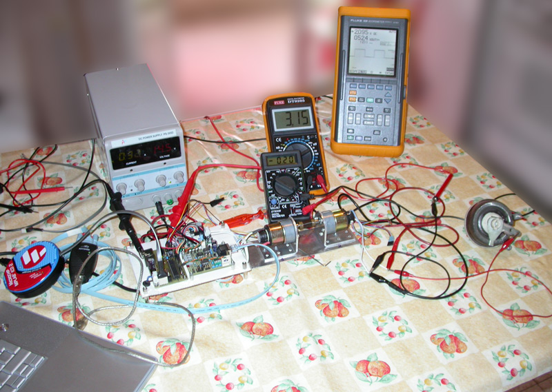
The test set used to obtain this graph is shown to the left. The software runs on a dsPIC30F4012 installed on a dsBoard. The load for the motor under test is an identical motor mechanically jointed axis by axis. This second motor acts as a generator and is connected to a power variable resistor to simulate load variations.
UART is used to receive commands from the Supervisor and to send it the results of the measurements. The communication portion of the program runs as a state machine. Status variables are used to execute actions in sequence. Very simple and fast Interrupt Service Routines (ISR) get or put every single byte from or to a buffer, and set the right flags to let the proper function to be executed.
TX I/O is disabled at init. It is setup as input at default, meaning in high impedance mode. This setup allows connecting both MCs TX ports together. They will be enabled one at a time by the Supervisor with INT1.
There is the same program in both MCs. Each MC is identified by an ID code to allow the Supervisor to send commands to the proper motor. At startup the program loops before the “main” idle loop, waiting for a Supervisor’s enable signal through CN5 I/O port. After that, the correct ID is assigned. Startup ID is 9 for both MCs.
The Supervisor will assign the definitive ID enabling subsequently each MC. Both MCs receive simultaneously data sent by the Supervisor, but only the addressed one (with the correct ID) will decode the message. A message with ID = 0 (broadcast) will be decoded by both MCs.
If any kind of error occurs during receiving (UART, checksum, parsing errors), the status variable is set to a negative number and the red led is powered up to communicate externally this fault condition. See “descrEng.txt” file in MPLAB project for a complete list of possible errors.
Below some links to the high resolution version of the flow charts for dsPID program, as well as the link to the whole MPLAB® IDE project written with MPLAB® C30 compiler, both (of course) by Microchip.