Searching on the Net to learn how to interface the bus installed in my home, I was really impressed by an open project realized
by an Italian guy that uses just one MCU to interface the bus and decode the signals: GuidoPIC.
Maybe because he is Italian, because he is named like me, because it uses my favorite microcontrollers (Microchip PIC), but I liked immediately that project and I started studying it.
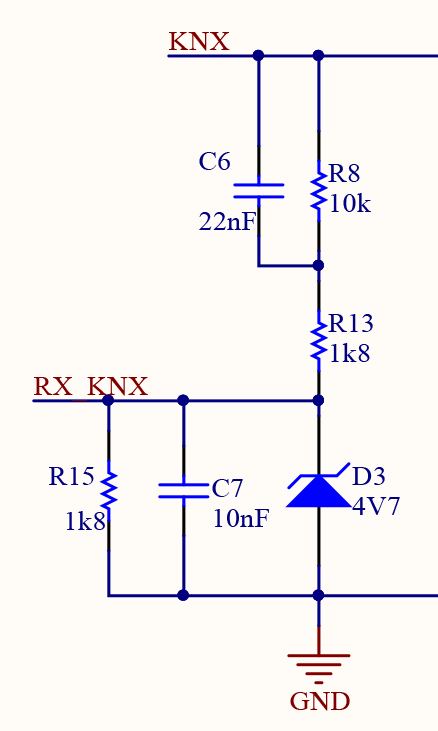
The circuit is very simple and the schematic diagram is self explaining. An R-C network, directly connected to the KNX bus, is used for incoming signal conditioning. A zener diode limits the 28V level to the one accepted by the MCU.
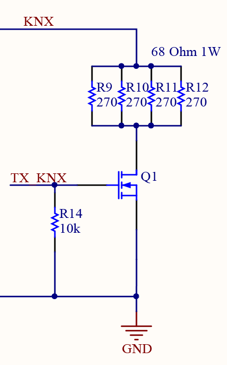
The transmission part is even simpler. A mosfet, directly driven by an MCU GPIO, connects to the ground the KNX positive line through a 68Ohm resistor. According to the Konnex specification, this is the way to modulate the bus.
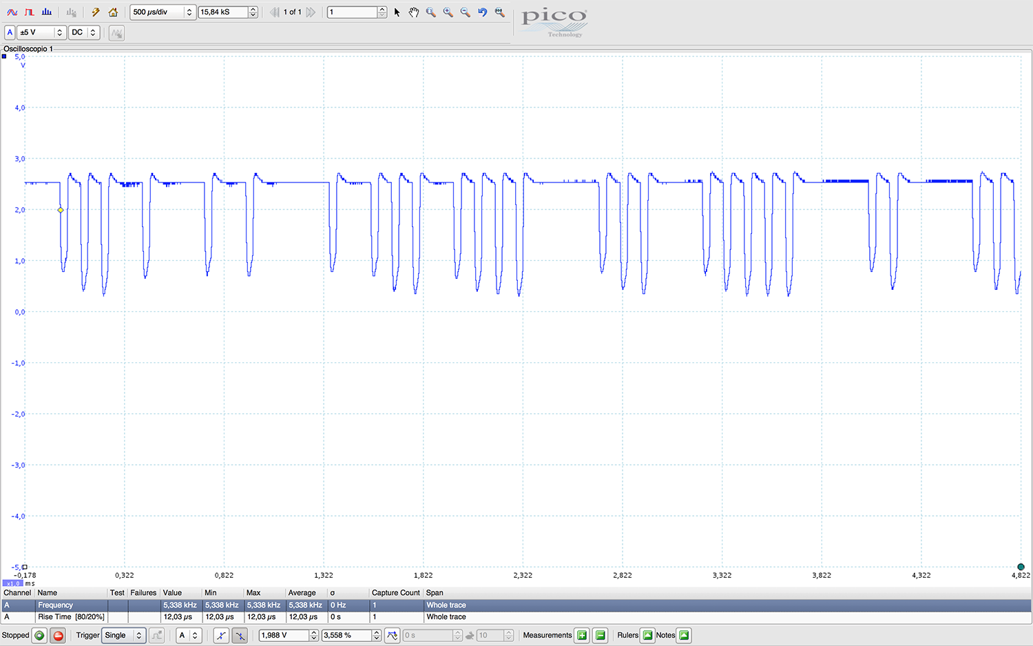
The resulting signal is visible on the scope output to the left. This level is suitable for the MCU I/O and can be directly connected to the pin for the software analysis using internal timers and comparators peripherals.
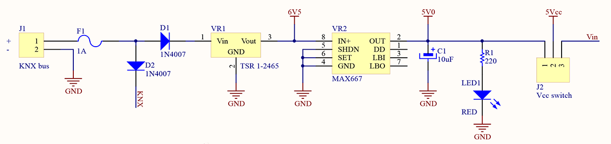
I've added to the original schematic a power supply that gets power directly from the bus. This works fine, good efficiency an no ripple at all because of the cascading LDO. But it has too much quiescent current, resulting in an overall current a little bit more than the KNX standard maximum admitted of 10mA for a single device. No problem for my own system, but it cannot be officially certified. A smaller switching regulator with very low quiescent current must be used.
Another change to the original schematic is about the serial interface. It has been optocoupled to insulate the bus from the higher level circuit.
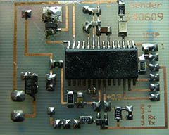
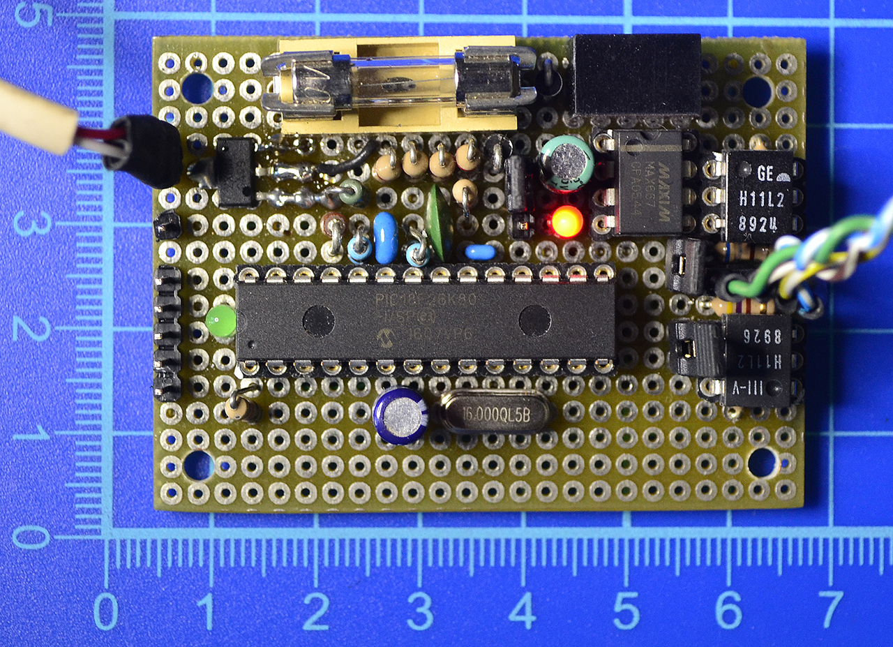
... and the correspondent circuit mounted on a perfboard to experiment.
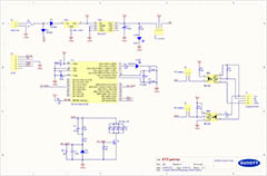
The resulting whole schematic diagram...