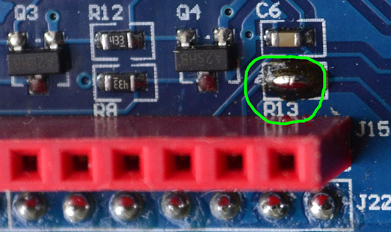
This specific board is very similar to many other GSM-GPRS shields available on the market. It uses the same chip and many of the instructions on these pages are valid for all of them. It also uses the same software power-on feature of the other boards but it's not well documented, the schematic is a little bit different. In order to enable this feature you must short circuit the pad marked as R13 close to the J15 header (expand the picture for details). In this case the Arduino sketch can power on the shield with a pulse on the pin 9 digital I/O. It is alway possible to switch it on and off manually via the S2 PWRKEY.
At the power on the PWR LED lights on. If a SIM is active and installed in the shield, After a while the Status LED also lights on steadily and NetLight LED start blinking rapidly. When the board joins the cell network the NetLight LED blinks slowly and you can start using the system.
GSM remote control
Not very much to say from the hardware point of view. Just put the shield over an Arduino. That's all.
I can just add some suggestions:
the communication module requires some power. It can be powered by the Arduino but the USB supply is not enough. You must connect a good power supply to the Arduino board, switch on the shield and start working. If the power supply is too weak the GSM board will switch off when trying to connect to the network.