Hardware
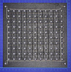
Many of the circuits found on the Net use a series of LEDs connected together in order to compose the words using few I/O lines. I wanted to have a general purpose circuit, usable for different languages. This leds of course to a LEDs matrix driven by X-Y I/O scanning with enough speed, to allow different languages just changing software and letters mask.
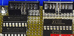
To drive the LEDs matrix directly with the PICs I/Os you need some drivers, both high side and low side. The high side drivers are used for the columns, the low side ones for the rows. The serial scanning is applied to the rows because they are less. The signals to the columns are parallel. This divides the frame period by ten instead of twelve, enabling an higher brightness of the LEDs: 10% of duty cycle instead of 8.3%.
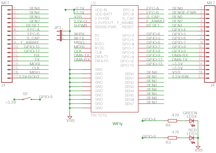
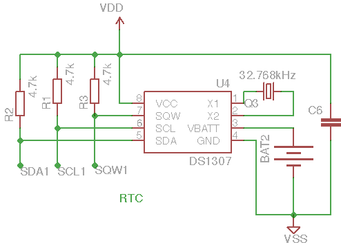
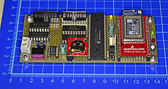
To correct the long term drift of the RTC, the time is synchronized via Internet to the INRIM reference through a Sparkfun WiFLy module.
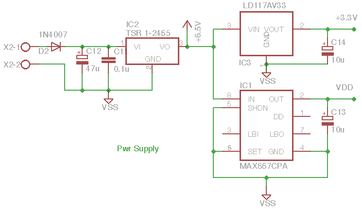
The generic wall adapter voltage (9 to 36V) is lowered down and stabilized to 6.5V with a very high efficiency through a switching regulator. Two linear regulators are used to supply WiFly at 3.3V and PIC18F4620 at 5V.