Pendulum
This project is almost useless, I want just to realize a pendulum that swings endless. Nothing more. No use at all. This is not an original project but my version of a project of the past century, already seen in many different ways on the Net.
#include <htc.h>
#define _XTAL_FREQ 4000000
__CONFIG(IOSCFS_4MHZ&MCPU_ON&WDT_ON&CP_OFF&MCLRE_ON);
volatile unsigned char control TRIS @ 0x06; // it is not declared in PICC 9.81
void main()
{
char Temp;
// Enable Wake-up on change on GP0-1-3, disable pull-up, prescaler 128 to WDT
OPTION=0b01001111;
ADCON0bits.ANS1=0; // GP1= digital
TRIS=0b11111011; // Set Only bit GP2=OUTPUT, GP1=INPUT
while(1)
{
// if the program starts because of interrupt or because of watchdog
// it kicks the pendulum
// __delay_ms(1); // wait for the best moment to kick
GP2=0; // ON, because of the PNP transistor it is inverted
__delay_ms(10); // kick time
GP2=1; // OFF
__delay_ms(30); // wait for the end
CLRWDT();
// read input pin before entering sleep, read datasheet for info
Temp=GPIO;
SLEEP();
}
}
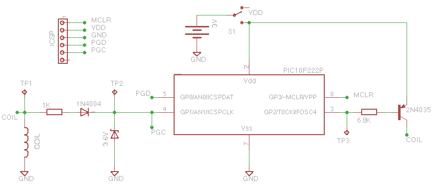


The same coil can be used both as a sensor and an actuator.
This is my first time with a so small PIC. It's very interesting. It can be used for a lot of different situations, substituting transistors, logic ports, NE555 and so on with a lot more flexibility.
For a small swinging pendulum, the period can be calculated with the formula:
2*PI*sqr(L/g)
where: L = pendulum length and g = acceleration of gravity (9.81 m/s^2).
In practice the PIC is awake for 10ms every 500ms for a 25cm long pendulum (2% duty cycle), 10ms every 1000ms for 1m long pendulum (1% duty cycle).
With a small pendulum the pulse can also be shorted because less energy is required, with an even less power consumption.
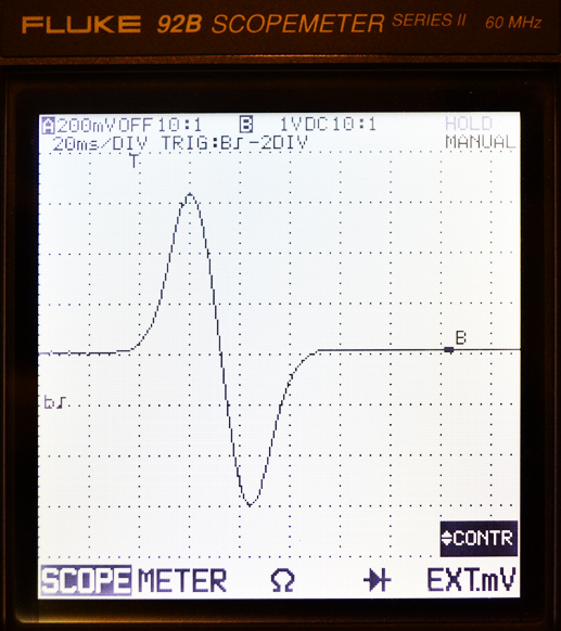
It is interesting to see how the shape and the amplitude of the signal varies using different type of magnets.
At TP2 the signal, compared to TP1 one, is rectified and amplitude limited by the Resistor-Diode-Zener network.
At TP3 we have the pulse that triggers the transistor for a new kick to the pendulum. I have used a PNP transistor to have a high side driving for the coil, so the pulse must be negative.
The PIC10F222 works fine in the 2 to 5.5V power supply range. The high level threshold for a digital input is related to the power supply. With 3V power supply we can see that the trigger starts when the voltage at GP1 rise above 1V. With a 5V power supply it needs an higher lever and therefore more time to start.
I have found the right delay for the kick and the right duration experimentally.
The goal #1 is fully achieved. I hope some one else can have fun too with this example.
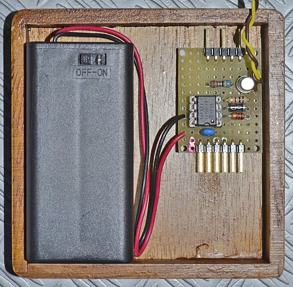
As the picture shows the circuit is very simple even on a perfboard. No quartz, very few external components. Most of the wires below the board are to connect ICSP and test plugs. Once programmed and tested they can be removed from the schematic saving even more space.
The basic theory is the same I've used. The balance wheel has permanent magnets and it is driven by a coil with a very simple electronic circuit. The electric pulse to the coil is synchronized with the balance wheel period by sensing the magnets. In this way we have an oscillating system that requires a very little amount of energy to keep moving. The power is provided by a battery instead of a spring. The rest of the gear mechanism is the same as a traditional clock.
I have always been fascinated by this kind of extremely simple mechanism. I'm collecting magnets, coils and everything that can be useful to realize it since a long time.

http://sound.westhost.com/clocks/free-pendulum.html
http://www.sciencetronics.com/geocities/electronics/projects/pendulum.html
http://www.trainelectronics.com/Pendulum/article.htm
I'm not alone! Which circuit may I use? None of them of course. I want my own system, using something more sophisticated like an MCU. Using one or two transistors doesn't add anything to my experience.
1) to have fun
2) to learn something more about PICs
3) to have a circuit that can be powered with just two AA batteries for a very long time.
4) to review some of the knowledge about physics I'm going to forget after so long time.
So, it is no so useless.
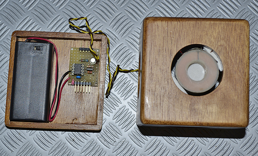
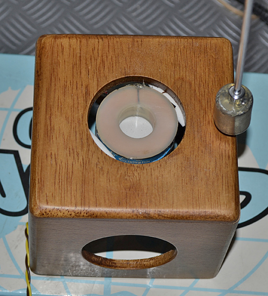
The magnet acts as the massive bob of the pendulum and the active part of the circuit too.
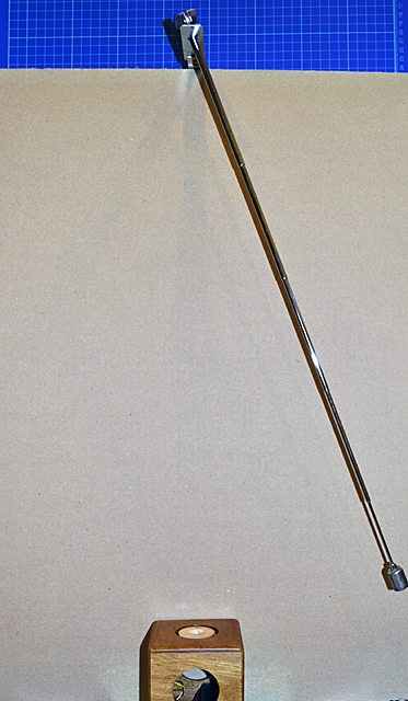
Using a telescoping antenna for the rod I'm free to fix the fulcrum everywhere and trim the exact length for the right position.
I've used MPLAB IDE with HI-TECH C compiler for PIC10/12/16 MCUs,
The configuration fuses sets internal clock to 4MHz, it is more than enough for our purposes and save some power compared to 8MHz clock. It also enables the watch-dog to increase reliability of the circuit.
The TRIS declaration is because of a bug in the include files of version 9.81 of the compiler.
With OPTION register it sets the "wake on input change" feature to restart the program from the sleep status when the magnet passes over the coil. The 1:128 prescaler is applied to watch-dog timer to have a 2.3s period for it.
When the program starts, for the first time, when input changes or for a WDT timeout, it reset the GP2 output enabling the PNP transistor that powers up the coil for 10ms. Then waits for the magnet passing away, to avoid another trigger of GP1, resets WDT, resets inputs for the next event and go to sleep.
That's all folk!
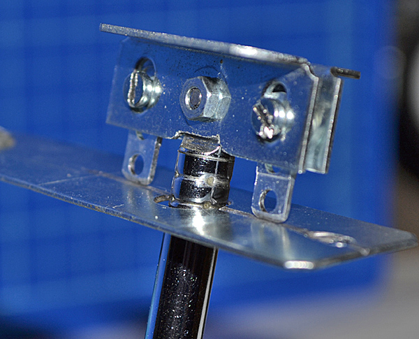
For this reason I've used a "knife" style fulcrum that adds very low friction still maintaining the right oscillating path.