f
updated on 17-02-2013
f
dsNav comm with IMU

dsNav

The communication between dsNavs

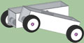
The navigation system is split in two parts, the front dsNav is the master one. It exchanges information with the IMU and decides the speed for front-right and front-left wheels to go in the right direction for the right distance.
Then it sends those values to the back dsNav, the slave one, in order to maintain perfectly paired the wheels on each side, i.e.: the back-right wheel always spins at the same speed of the front-right one, as well as the back-left and front-left wheels.

To the right the communication schema among all of the robot boards. The dsNav master board talks with the dsNav slave board via a serial communication (UART 2), and with the IMU via I2C bus.
The original schematic was designed for a RS485 alternative to a normal serial communication, with the optional connection to a SN75176 driver selectable with some soldering pads.
The I2C module shares some I/O pins with the UART 1 module and the I/O pin used for RS485 DIR signal too. With a little modification the same socket can be used alternatively for UART 1 or I2C.

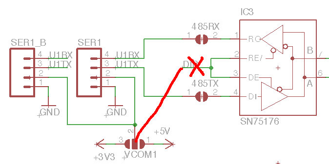
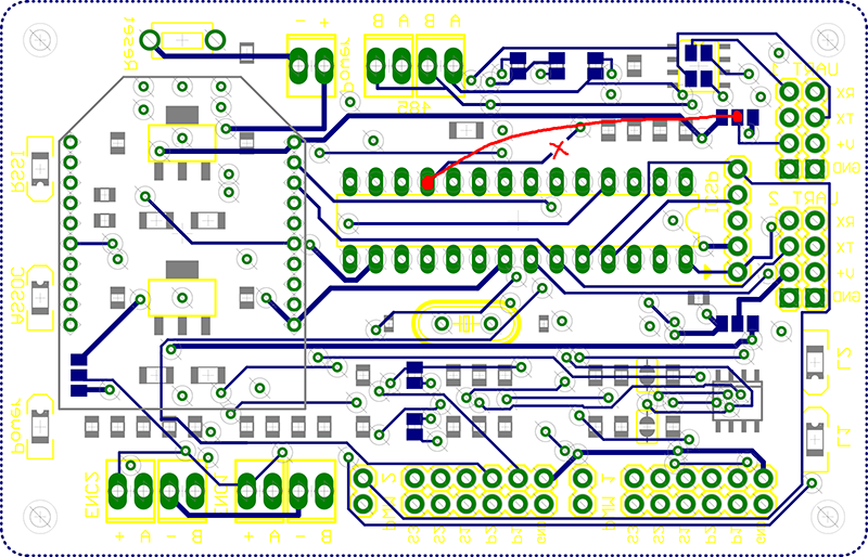
The modification needs just a cut to the original track and a wire soldered between to existing pads.
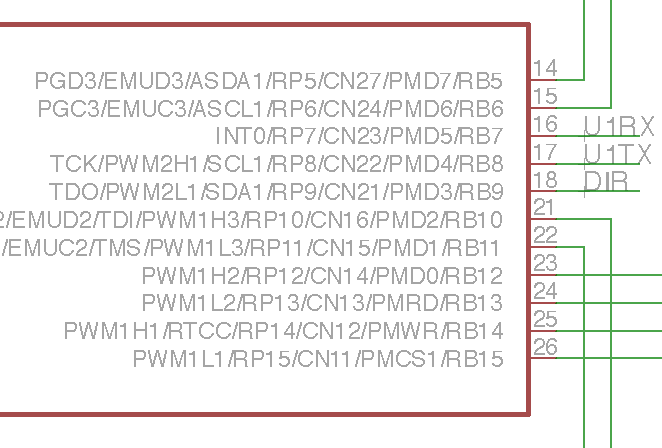
If the pins are used for UART1, use pin 1for GND, pin 3 for TX and pin 4 for RX. For I2C, use pin 1 for GND, pin 2 for SDA and pin 3 for SCL.

Of course the Vcom features of the original circuit cannot be used anymore.

The I2C slave code for the dsPIC33F is a porting of the PIC18F version. The I2C peripherals in the new PIC 18F series and in the PIC 24F/dsPIC33F series are very similar. A Microchip document explains the differences. The PIC 24F/dsPIC33F I2C module is more powerful because it has separate buffers for TX and RX, allowing a simultaneous master and slave behavior. This also simplify the code in the dsPIC33 version.

The whole MPLAB X project
of the software containing I2C procedures for dsPIC33
is available as an open source at
Google code repository